

 Send Email
 Whatsapp


Introduction
Choosing Pv Extension Cables is more than a matter of length or connector style. To match them correctly with different solar panels, you need to check conductor size, voltage and current ratings, connector compatibility, insulation type, and environmental durability so the system can carry power safely and efficiently. This article explains the key specifications that determine whether a cable will work with a given panel, where mismatches commonly occur, and how those errors affect energy yield, reliability, and fire risk. By the end, you’ll have a practical framework for selecting extension cables that fit both the electrical demands and physical layout of a solar installation.
Why PV Extension Cable Compatibility Matters
Whether outfitting a 5kW residential rooftop system or a 50MW utility-scale solar farm, ensuring compatible PV extension cables matching is fundamental to both system performance and site safety. Solar panels generate direct current (DC) electricity, which must travel efficiently from the module array to the inverter or charge controller. Because DC systems are highly susceptible to resistance over long transmission distances, the physical and electrical characteristics of the wiring infrastructure cannot be treated as an afterthought. Proper matching prevents severe bottlenecks in energy yield and mitigates substantial fire risks associated with high-voltage DC.
Key Definitions to Clarify Early
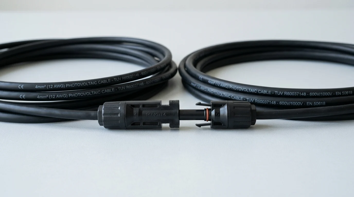
Understanding industry terminology is the first step toward achieving seamless system integration. The cross-sectional area of the conductor, typically measured in American Wire Gauge (AWG) or square millimeters (mm²), strictly dictates the maximum current the wire can safely carry. Standard residential and commercial solar installations predominantly utilize 4mm² (12 AWG) or 6mm² (10 AWG) cables, which are constructed using stranded, tinned copper to resist oxidation. Additionally, the solar industry relies heavily on standardized contact mechanisms. The ubiquitous MC4-style connectors feature specific male and female interlocking designs that must mate perfectly to maintain an airtight and watertight seal against environmental elements.
Common Risks of Mismatched Cables
Deploying incompatible or substandard components introduces severe operational and fire hazards. If a cable is undersized for the solar panel's short-circuit current (Isc), the resulting electrical resistance generates excessive localized heat. Temperatures at poor connection points can rapidly exceed the standard 90°C to 120°C insulation rating of the wire jacket, significantly increasing the risk of melting, arc faults, or devastating electrical fires. Furthermore, mismatched connectors from different manufacturers can lead to micro-gaps, permitting the ingress of moisture. This causes accelerated corrosion and a voltage drop exceeding the acceptable industry threshold of 2% to 3%. This inefficiency translates directly into measurable, continuous power loss over the 25-year lifespan of the solar array.
Technical Criteria for Matching PV Extension Cables
Selecting the appropriate wiring requires a rigorous, data-driven evaluation of the system's electrical specifications. Modern high-efficiency solar modules frequently operate at elevated voltages to maximize transmission efficiency, necessitating cables explicitly rated for 1000V DC or 1500V DC environments. Failing to align the extension cable's specifications with themaximum system voltage and peak amperage output of the solar array can compromise the entire infrastructure and void costly equipment warranties.
How to Compare Connectors, Conductor Size, and Ratings
The primary technical factors in cable selection are connector compatibility, conductor cross-section, and environmental resilience ratings. Installers must verify that the extension cables utilize the exact same connector standard and tolerance as the solar panels—typically original Stäubli MC4 or certified compatible variants—to ensure a secure, IP67- or IP68-rated weatherproof connection. Conductor size must be calculated based on the maximum series current; for instance, a 10 AWG cable can safely handle up to 30 amps in a standard conduit, whereas a 12 AWG cable is generally limited to 20 amps under the same thermal conditions. Additionally, the outer jacket must feature UV-resistant cross-linked polyethylene (XLPE) or cross-linked polyolefin (XLPO) to withstand decades of direct sunlight exposure, extreme temperature fluctuations, and ozone degradation without cracking.
What a Cable Comparison Table Should Include
To streamline the procurement and engineering process, project managers should utilize a standardized matrix to evaluate potential wiring solutions against the site's layout. A comprehensive comparison table must detail conductor sizing, maximum current capacity, and recommended distance limits to prevent excessive power loss during peak generation hours.
| Cable Size | Max Ampacity | Max Voltage Rating | Recommended Max Run (10A, <3% Drop) |
|---|---|---|---|
| 4mm² (12 AWG) | 20A | 1000V DC | 15 meters (50 feet) |
| 6mm² (10 AWG) | 30A | 1500V DC | 23 meters (75 feet) |
| 10mm² (8 AWG) | 45A | 1500V DC | 40 meters (130 feet) |
| 16mm² (6 AWG) | 65A | 1500V DC | 65 meters (213 feet) |
Such matrices help ensure that the selected components strictly adhere to the electrical demands of the specific solar array configuration. When planning runs that exceed 40 meters, system designers must transition to heavier gauge wiring to keep the total system voltage drop well below the 3% maximum tolerance mandated by most international electrical codes.
How to Verify Sourcing and Installation Fit
Beyond theoretical specifications and sizing charts, securing reliable materials demands a stringent vetting process during procurement and delivery. Sourcing the right components involves balancing regulatory compliance, supply chain logistics, and physical installation requirements to guarantee long-term performance and safety for the end user.
A Step-by-Step Buyer Verification Process
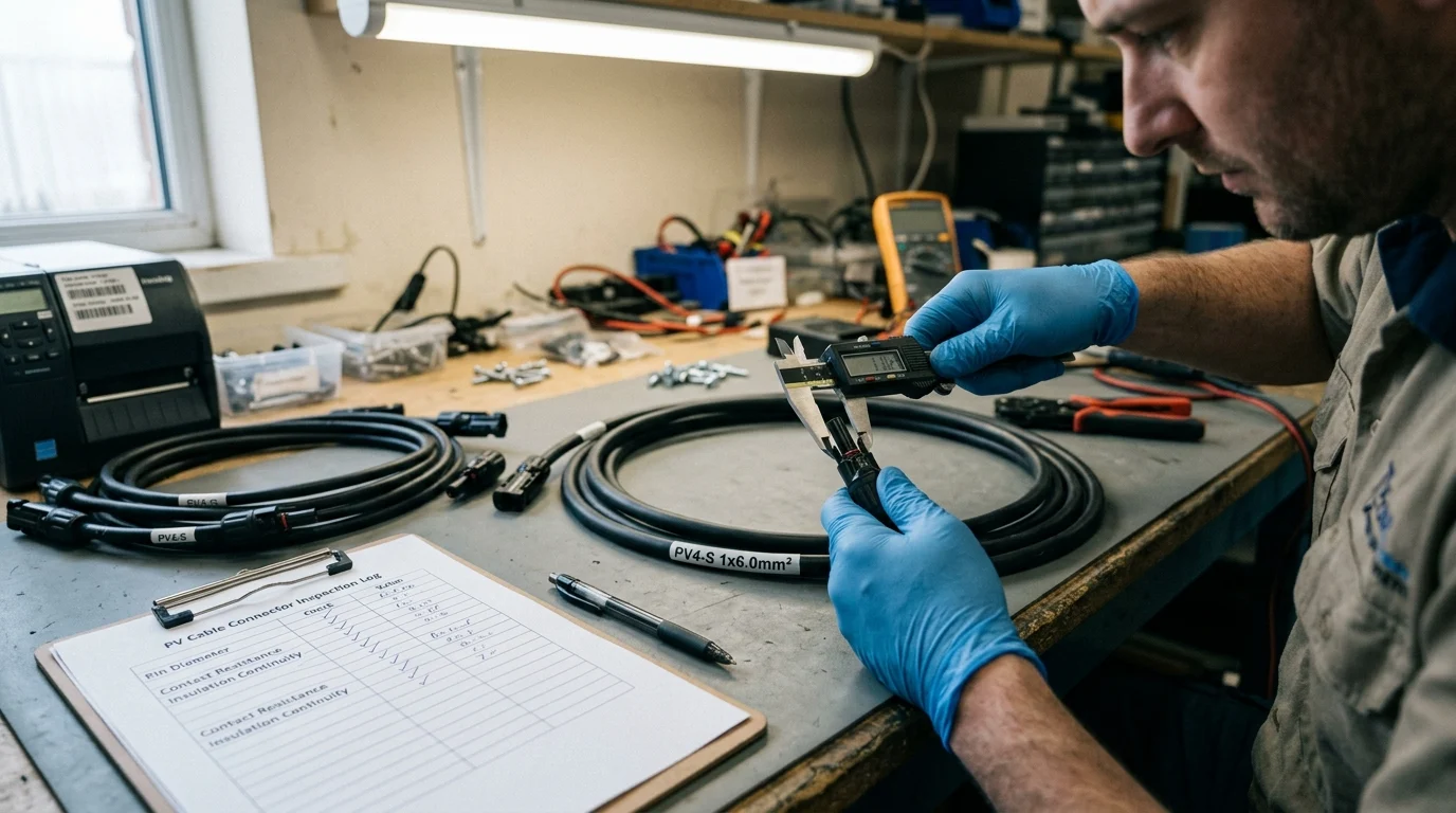
A systematic verification process begins with comprehensively auditing the manufacturer's laboratory certifications. Commercial buyers must demand proof of compliance with safety standards such as UL 4703 in North America or EN 50618 in Europe, which dictate rigorous testing for PV Wire durability, flame retardance, and mechanical strength. Next, evaluate the supply chain parameters; enterprise buyers should account for typical Minimum Order Quantities (MOQs) ranging from 1,000 to 5,000 meters for custom cable lengths, alongside manufacturing lead times that can span 3 to 6 weeks depending on global copper availability. Upon delivery, field technicians must conduct a visual and mechanical inspection. This includes utilizing a digital multimeter to test for end-to-end continuity and verifying that the connector locking mechanisms engage with a distinct, audible click. A proper connection should also pass a standard pull-strength test, resisting a minimum pull-out force of 89 Newtons without separating.
How to Evaluate Trade-Offs Before Final Selection
Decision-makers frequently face complex trade-offs between upfront capital expenditure and long-term energy yield. While thicker gauge cables and premium connectors may marginally increase initial project costs, they minimize voltage drop and prevent costly maintenance interventions over the system's 25-year lifespan.
Key Takeaways
- The most important conclusions and rationale for compatible PV extension cables matching
- Specs, compliance, and risk checks worth validating before you commit
- Practical next steps and caveats readers can apply immediately
Frequently Asked Questions
How do I know if a PV extension cable matches my solar panel connectors?
Check that both use the same connector standard and exact mating tolerance, ideally original MC4 or certified compatible MC4-style connectors for a sealed IP67/IP68 connection.
What cable size is commonly used for residential solar panels?
Most residential systems use 4mm² (12 AWG) or 6mm² (10 AWG) stranded tinned copper, chosen based on panel current and cable run length.
Should I choose 1000V DC or 1500V DC PV extension cables?
Match the cable to your system’s maximum DC voltage. Use 1500V-rated cable for higher-voltage arrays; never use a lower voltage rating than the array requires.
How can I reduce voltage drop in PV extension cable runs?
Use a larger conductor and keep runs as short as practical. Aim to stay within about 2% to 3% voltage drop for better long-term energy yield.
What cable jacket material is best for outdoor solar installations?
Choose PV cable with UV-resistant XLPE or XLPO insulation. It handles sunlight, ozone, and temperature swings better than general-purpose wire outdoors.